Saturday, September 29, 2012

WhiteAnt 3d Printer Build- Full Bed Test Print

This test will use the maximum printable area of the print bed which is 360mm x 240mm. I  created a model in Google SketchUp that fills an area 350mm x 220mm (13.8" x 8.7"). The walls are 10mm high and 8mm thick and the outer diameter of the circle is 40mm.


Here is the print data:

Extruder Nozzle: .5mm
Print Layer Thickness: .4mm
25 layers
Infill solidity ratio: 0.1
77,750 lines
15,670 filament length
Heat bed (center ref. point) temp. 61-65c
Ambient temp. 27.5c
Print Time: 4hr 32min


Critique:

Overall the first print run using the full bed was a success, but there are some trouble points that need to be mentioned.
1) a fine tuning of the axes calibration if precise pieces are required. The
X-axis measures 350mm as the model, but the Y-axis measures 5mm wider.
2) slight warping at the corners, but unobtrusive overall.


3) an odd separation of the perimeter walls toward the bottom right hand corner.


4) about 30mm inward from all 4 corner points the printing is rough.


Thursday, September 27, 2012

WhiteAnt 3d Printer Build- Calibration

I spent a long time working out the calibration on my Mendel Prusa 3d printer. I had numerous problems with the electronics and the software and I didn’t have a working reference point to help solve them. This is one reason why I kept many of the familiar systems of my Prusa Mendel printer as a part of this modified WhiteAnt printer.

The calibration for the modified WhiteAnt hasn’t been difficult.

I'm using Kiliment-Sprinter-a352585 firmware with  Pronterface. Here are the following changes I made from my Prusa Mendel setup:
In Pronterface, I increased the print bed. This can be done by opening the options window from the settings tab and changing the build dimensions. In my case, instead of 200mm x 200mm x 80mm, I placed the values 360mm x 240mm x150mm.

In the firmware, I changed the build envelope size. Under the tab Configuration.h these values were substituted:
Const int X_MAX_LENGTH = 360;
Const int Y_MAX_LENGTH = 240;
Const int Z_MAX_LENGTH = 150;

Next I set the calibration for the X,Y,Z, and E steps. For my Prusa Mendel they were:
axis_steps_per_unit[] = {79.207, 80, 2568, 1394};
For the modified WhiteAnt the values were substituted with these:
axis_steps_per_unit[] = {39.9, 40.90, 329, 1300};

Interestingly, the X,Y values are half of the original values when the stepper motor is increased one size up. The Z-axis is way off due to changing from a metric 8mm rod with a 1.25 pitch to a SAE 3/8" lead screw with 10 threads per inch. The extruder is basically the same since no change in that system was made.


These are all of the changes that I made. All my previous Skeinforge and Pronterface settings I left in place. There is always room for improvement, but for now I’m happy to keep my setup at it’s present configuration. 


Tuesday, September 25, 2012

WhiteAnt 3d Printer Build- Reinforcing the Structure

It's not fair for me to criticize the structural integrity of the WhiteAnt design because I modified it and since I haven’t built the original design (or physically seen it in action), I have no basis to make an opinion. My modified WhiteAnt needs structural reinforcement. There is severe vibration along the x-axis and the legs of the printer during xy-axis movement.

In order to dampen this, I mounted the legs to a base made of 3/4" thick MDF.


The back plate of the printer is screwed into a box which covers the back end of
the printer (where the print bed extends along the y-axis). This adds substantial
support to x-axis rail.


Sunday, September 23, 2012

WhiteAnt 3d Printer Build- Extruder and Hot End

The original WhiteAnt 3d printer specified to use it's own extruder design that is fabricated from wood and a MakerBot hot end. I decided to use a MakerGear plastruder and hot end.

In order to do this I first had to change the heat core of the hot end. The typical MakerGear hot end uses a brass core which is wrapped in nichrome wire and coated with a ceramic adhesive. The 30 awg nichrome wire is cut to length which will give about 6 ohms resistance. In a 12v system this will make a 24 watt heater.

My system is running off of 24v. To achieve the same wattage as the typical MakerGear heat core the total resistance of the nichrome wire will have to be increased. By using Ohm's Law, w=v^2/r=24v^2/24r=24 watts,  it's discovered that the length of the nichrome wire needs to equal 24 ohms (an increased by 4 times). This is a lot of wire to wrap around the brass core. To help decrease the length, I switched to a 31 awg nichrome wire which increases the resistance from 6.5 ohms to 8.2 ohms per foot. This shaved off about a 1/4 of length.


No portion of the WhiteAnt extruder mount is useful for the MakerGear plastruder, so a mounting device had to be designed. I used a Simpson Strong Tie Z-Max Angle and cut a shape which supports the plastruder assembly and  allows for the hot end to protrude from the bottom.


I also added 4 LEDs at the bottom of the plate which will give ample illumination during a print build.


Thursday, September 13, 2012

WhiteAnt 3d Printer Build- Electronics III

Mounted at one end of each axis’ path of travel is a small switch. This is generally referred to as a limit or stop switch and it’s purpose is to signal a “home” point of reference. The original WhiteAnt plans called for the Z-axis switch to be mounted on the bottom end of the X carriage, triggered when the switch makes contact with a screw protruding from the Strong-Tie assembly of the Z-axis. This would make “home” at the furthest point from the printer’s bed.

I find this odd and rather perplexing.

Instead, I replaced one of the bolts holding the Z-axis motor mount assembly with a 3/8” threaded rod cut to a length to where a limit switch could be triggered by a nut. By adjusting the position of the nut on the threaded rod, easy calibration can be made of the extruder’s hot end. The other 2 limit switches were mounted basically as was originally designed.


Before


After


Noise. The fluctuation of electronic signals.

There seems to be a lot of opinion concerning the shielding of noise among CNC users. I don't remember this as a concern when I did research on my Prusa Mendel build. Because I wasn’t aware of using shielded cable, I didn’t and my RepRap printer has worked fine.
I decided to use shielded cable on this printer.


For convenience, I added D-sub connectors so that the electronics can be easily removed from the printer.


Now that I have most of the electronics connected, I did a test drill by running a print routine for a small object. No calibration has been made in the firmware.

Friday, September 7, 2012

WhiteAnt 3d Printer Build- Electronics II

The heart of the 3d printer's electronics system is an Arduino Mega 2560 microcontroller interfaced by a RAMPS 1.2 shield. The RAMPS (RepRap Arduino Mega Pololu Shield) attaches to the topside of the Arduino Mega and allows for connections to the Pololu stepper drivers, motors, heat and fan components. Presently, the version of the board is at 1.4.

Arduino Mega 2560 and Arduino Mega 2560 with attached RAMPS 1.4 shield.


Why am I using a shield designed for Pololu stepper drivers if I plan to use
different drivers? First and foremost, I want to keep with an electronics
package that is working well with the software that I am presently using. My
past experience had a high learning curve because I was completely unfamiliar
with the many different components (both soft and hardware related). Getting all
of it to work together was not easy. I'm hoping by retaining most of my original
setup on this printer, I'll be able to work bugs out more efficiently.

Second, the RAMPS shield is considered to be the best interface for the RepRap printers and because of this, has a good support system (especially where software is concerned).

Third, I plan to retain the use of 1 and later 2 Pololu drivers for extruder
control. More than half of the shield then keeps it’s functionality as it was
designed.

I'm using RAMPS version 1.2 (later I will update to v1.4) for the initial build
of the WhiteAnt. The v1.2 shield was assembled with only one important
alteration:  the IN4004 diode was omitted so that the board can be powered by
24v. All of the driver slots are left in place and will be used as designed.


Fully assembled RAMPS 1.2


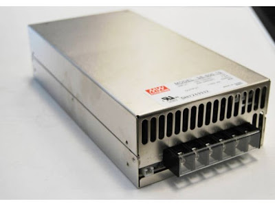
Why power the shield with 24v instead of the typical 12v supply? The RepRap
printers use the NEMA 17 stepper motors to move the axes. The WhiteAnt is built
utilizing the larger stepper motors NEMA 23. These larger motors will work more
effectively if more voltage is supplied.

Nema 17 and NEMA 23 stepper motors.


The Pololu 4988 stepper drivers (typically used on the RAMPS shield) are rated
to 35v, 2A and could drive the larger motors, but the higher current demands
would put a strain on them. Overheating would be a constant problem. I'm
replacing the Pololu’s with the v3.3 stepper drivers designed by Makerbot. They
are rated up to 35v, 2.8A and robust enough to handle the NEMA 23's.


Makerbot v3.3 and Pololu 4988 stepper drivers.

The major obstacle in swapping out the Pololu with the Makerbot stepper driver
is the hookup to the RAMPS shield. What connections are necessary? I owe NoobMan on the RepRap forums thanks for helping me sort it out. A detailed account can be found here. Basically, the DIR, STEP, ENABLE pins (ignore the other 3 pins) are connected from the Makerbot driver to the corresponding pins on the RAMPS board (where the Pololu driver would sit).
The 12v power pins on the Makerbot board (even though 24v will be supplied in this case) are connected to the motor power supply pins (where the Pololu would sit) on the RAMPS shield. This supplies power to the Makerbot driver. All of the other connections that the Pololu driver would use can be ignored including the motor connections next to the driver slot. All four stepper motor leads will now be connected directly on the Makerbot driver.

The next obstacle is finding a way to physically attach the connections. One method to solve this is by imitating the Pololu driver. I fabricated little boards with male breakaway headers and wired into it. This gives me the flexibility of swapping  out whatever driver I decide to use.


To test my system, I hooked up a driver and stepper motor to the Y-axis and connected the Arduino Mega to the PC. Using the 3d printer software Pronterface, I was able to run the motor with the y-axis controls. The motor 
worked well in both directions.


Sunday, September 2, 2012

WhiteAnt Build- Electronics I

Configuring the electronics for this printer has been the most difficult part of this build to date. From the beginning I had decided to stay with the familiar RAMPS shield (for the Arduino Mega 2560) that I use to operate my Mendel Prusa, but with two major deviations: a 24v system (instead of a 12v) and different stepper drivers (other than the Pololus) for the axes.
The RAMPS shield was designed specifically for the use of Pololu drivers, so why use it? I have my reasons for doing this and I think once I outline my process and make my intentions clear for this particular setup it will make some sense.

After googling for countless hours, it seems that there is no information of any practical use that documents this procedure. There's some talk of others doing it, with vague, partial descriptions, but nothing that has helped me. For someone not familiar with this technology, it can be very confusing when you have a variety of stepper drivers available that designate their 10 or more connectors with different labels like DIR, Enable, PUL, STEP, Sleep, DISABLE, and others.
According to the most popular google results, apparently all you have to do is plug in the DIR and STEP and it works (so what’s up with all the other connections?). My Polulu A4988 drivers (that are typically used on the RAMPS board) uses STEP, DIR, Enable, Sleep and Reset are set together, voltages IN and the 4 connectors for the motor. Later I will illustrate how I plan to make this work with different stepper drivers.


First, I needed a 24v DC power supply and here’s where I made an error in judgement: I tried to adapt (2) ATX power supplies in piggyback for a 24v DC source.


ATX power supplies

There's a plethora of websites showing the conversion for a 12 volt supply and I have one that I converted when I built my Prusa Mendel. It's worked great. There is far less information about converted piggybacked supplies and once again the information isn’t always clear. There is one really good YouTube video here that
explains the process well, but I suppose not well enough for me at the time. My mistake cost me 2 Arduino Megas and a Geckco g251 stepper drive (ouch!).


2 dead Arduino Megas and a Gecko G251


So why did my power supply burn out my Arduinos?

After much bench testing (to no avail) I did some research and found on the
RepRap forum (here) an entry where someone else had mysteriously killed 2
Arduino Megas. It was discovered that this person was getting a potential
difference between his Arduino ground and power supply ground: where it should
be 0v on the rail he was getting  -12v. I did a quick test and measured the ground from my USB computer connection (PC is powered ON) and my power supply negative lead (power supply in piggyback and ON) and my reading was a -12v (there shouldn't be a voltage there).
 I burned out my Arduino Megas because of one simple mistake: part of the conversion of 2 ATX power supplies wired in series requires one unit to have the earth ground disconnected. I started my piggyback series with the power supply with the disconnected earth ground first (the power supply with the unmodified AC connector should had been placed first in series).

I should have known better and for more than one reason: don't skimp on one of the most important aspects of a sensitive electronics system. Have a good power supply that is clean of fluctuation and noise. I bought a Mean well 24v 600w power supply. It wasn't cheap, but neither were the Arduinos and Gecko.


Mean Well 24vDC 600w power supply