
Configuring the electronics for this printer has been the most difficult part of this build to date. From the beginning I had decided to stay with the familiar RAMPS shield (for the Arduino Mega 2560) that I use to operate my Mendel Prusa, but with two major deviations: a 24v system (instead of a 12v) and different stepper drivers (other than the Pololus) for the axes.
The RAMPS shield was designed specifically for the use of Pololu drivers, so why use it? I have my reasons for doing this and I think once I outline my process and make my intentions clear for this particular setup it will make some sense.
After googling for countless hours, it seems that there is no information of any practical use that documents this procedure. There's some talk of others doing it, with vague, partial descriptions, but nothing that has helped me. For someone not familiar with this technology, it can be very confusing when you have a variety of stepper drivers available that designate their 10 or more connectors with different labels like DIR, Enable, PUL, STEP, Sleep, DISABLE, and others.
According to the most popular google results, apparently all you have to do is plug in the DIR and STEP and it works (so what’s up with all the other connections?). My Polulu A4988 drivers (that are typically used on the RAMPS board) uses STEP, DIR, Enable, Sleep and Reset are set together, voltages IN and the 4 connectors for the motor. Later I will illustrate how I plan to make this work with different stepper drivers.
First, I needed a 24v DC power supply and here’s where I made an error in judgement: I tried to adapt (2) ATX power supplies in piggyback for a 24v DC source.
So why did my power supply burn out my Arduinos?
After much bench testing (to no avail) I did some research and found on the
RepRap forum (here) an entry where someone else had mysteriously killed 2
Arduino Megas. It was discovered that this person was getting a potential
difference between his Arduino ground and power supply ground: where it should
be 0v on the rail he was getting -12v. I did a quick test and measured the ground from my USB computer connection (PC is powered ON) and my power supply negative lead (power supply in piggyback and ON) and my reading was a -12v (there shouldn't be a voltage there).
I burned out my Arduino Megas because of one simple mistake: part of the conversion of 2 ATX power supplies wired in series requires one unit to have the earth ground disconnected. I started my piggyback series with the power supply with the disconnected earth ground first (the power supply with the unmodified AC connector should had been placed first in series).
I should have known better and for more than one reason: don't skimp on one of the most important aspects of a sensitive electronics system. Have a good power supply that is clean of fluctuation and noise. I bought a Mean well 24v 600w power supply. It wasn't cheap, but neither were the Arduinos and Gecko.
The RAMPS shield was designed specifically for the use of Pololu drivers, so why use it? I have my reasons for doing this and I think once I outline my process and make my intentions clear for this particular setup it will make some sense.
After googling for countless hours, it seems that there is no information of any practical use that documents this procedure. There's some talk of others doing it, with vague, partial descriptions, but nothing that has helped me. For someone not familiar with this technology, it can be very confusing when you have a variety of stepper drivers available that designate their 10 or more connectors with different labels like DIR, Enable, PUL, STEP, Sleep, DISABLE, and others.
According to the most popular google results, apparently all you have to do is plug in the DIR and STEP and it works (so what’s up with all the other connections?). My Polulu A4988 drivers (that are typically used on the RAMPS board) uses STEP, DIR, Enable, Sleep and Reset are set together, voltages IN and the 4 connectors for the motor. Later I will illustrate how I plan to make this work with different stepper drivers.
 |
| ATX power supplies |
There's a plethora of websites showing the conversion for a 12 volt supply and I have one that I converted when I built my Prusa Mendel. It's worked great. There is far less information about converted piggybacked supplies and once again the information isn’t always clear. There is one really good YouTube video here that
explains the process well, but I suppose not well enough for me at the time. My mistake cost me 2 Arduino Megas and a Geckco g251 stepper drive (ouch!). |
| 2 dead Arduino Megas and a Gecko G251 |
So why did my power supply burn out my Arduinos?
After much bench testing (to no avail) I did some research and found on the
RepRap forum (here) an entry where someone else had mysteriously killed 2
Arduino Megas. It was discovered that this person was getting a potential
difference between his Arduino ground and power supply ground: where it should
be 0v on the rail he was getting -12v. I did a quick test and measured the ground from my USB computer connection (PC is powered ON) and my power supply negative lead (power supply in piggyback and ON) and my reading was a -12v (there shouldn't be a voltage there).
I burned out my Arduino Megas because of one simple mistake: part of the conversion of 2 ATX power supplies wired in series requires one unit to have the earth ground disconnected. I started my piggyback series with the power supply with the disconnected earth ground first (the power supply with the unmodified AC connector should had been placed first in series).
I should have known better and for more than one reason: don't skimp on one of the most important aspects of a sensitive electronics system. Have a good power supply that is clean of fluctuation and noise. I bought a Mean well 24v 600w power supply. It wasn't cheap, but neither were the Arduinos and Gecko.
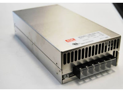 |
| Mean Well 24vDC 600w power supply |
No comments:
Post a Comment