
For the Printrbot I've decided to use a Sanguinololu v.1.3a controller. It’s equipped with the ATMEGA 1284 chip and Pololu driver clones.
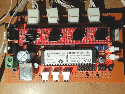
The primary reason for this setup and not an Arduino Mega with RAMPS shield is because there isn’t much room to place all the components under the print bed. The Sanguinololu is a slim all-in-one unit (minus the drivers).

I added a 4.5" x 6" PCB heat bed.

For the LED indictor I used SMD components.
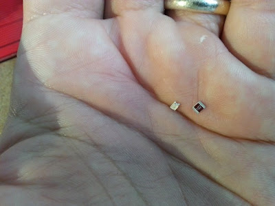
Because of their tiny size, it’s not exactly the greatest choice when a soldering iron is the only tool I have, but I found that by adding a little solder flux and adding little mounds of solder to the board connections first is the easiest way to accomplish this. Placing the components next and then heating the connectors with the fine tip of an iron will remelt the solder underneath and make a good bond.

For this printer, I’d like to use a PWM fan. This is a fan that uses pulse-width modulation to control it's speed. Since I plan to be printing with a lot of bridging techniques that may require G-code implemented cooling procedures using a fan, this is a necessity. Unfortunately, the Sanguinololu doesn’t have the required hookup for a PMW fan. To get around this, a separate circuit must be made. I used the circuit outlined here www.thingiverse.com/thing:22202. I did make some changes: I eliminated the 0.1uF capacitor and swapped out the RF540A MOSFET with a STP55NF06L MOSFET. This is the same MOSFET that’s used on the RAMPS board and is sufficient for use here as well.

This is the first 3D printer replication that I've made. All the plastic parts were made on my Prusa Mendel with some minor parts made with the RepRapPro.

In order to make the electronics work with my preferred host (Printrun) some changes will have to be made in the firmware. This’ll be covered in the next post.
The primary reason for this setup and not an Arduino Mega with RAMPS shield is because there isn’t much room to place all the components under the print bed. The Sanguinololu is a slim all-in-one unit (minus the drivers).
For the LED indictor I used SMD components.
Because of their tiny size, it’s not exactly the greatest choice when a soldering iron is the only tool I have, but I found that by adding a little solder flux and adding little mounds of solder to the board connections first is the easiest way to accomplish this. Placing the components next and then heating the connectors with the fine tip of an iron will remelt the solder underneath and make a good bond.
For this printer, I’d like to use a PWM fan. This is a fan that uses pulse-width modulation to control it's speed. Since I plan to be printing with a lot of bridging techniques that may require G-code implemented cooling procedures using a fan, this is a necessity. Unfortunately, the Sanguinololu doesn’t have the required hookup for a PMW fan. To get around this, a separate circuit must be made. I used the circuit outlined here www.thingiverse.com/thing:22202. I did make some changes: I eliminated the 0.1uF capacitor and swapped out the RF540A MOSFET with a STP55NF06L MOSFET. This is the same MOSFET that’s used on the RAMPS board and is sufficient for use here as well.
This is the first 3D printer replication that I've made. All the plastic parts were made on my Prusa Mendel with some minor parts made with the RepRapPro.
In order to make the electronics work with my preferred host (Printrun) some changes will have to be made in the firmware. This’ll be covered in the next post.
No comments:
Post a Comment