It's taken a lot longer to refine my setup for the DAVID laserscanner software than I expected. It's been more than a month since I experimented with the free edition of the software and a temporary rigging setup that I assembled (with an inexpensive red line laser and NEMA 17 stepper motor). Since then, I've purchased the Pro USB version of the software from a U.S. reseller (mydigitaldiscount- their stock goes fast. Mine was on back order for awhile). I also refined my rigging, components, and assembled an electronic control console.
Here's an overview of the components:
I designed all the structural components using 3/8" aluminum rods and plastic
parts modeled with Google SketchUp and printed on my Prusa Mendel 3d printer.
Calibration Panel
The plastic brackets can slide along the rods for the adjustment of larger
calibration panels. The rods themselves can be replaced with longer ones for
even bigger panels.
Turntable
The turntable is basically a round platform attached to a NEMA 17 stepper motor.
The structure can be adjusted in height by replacing the rods with longer ones.
Also the round platform can be switched out with one that's larger.
Laser and Camera Rig
I changed my original 2 rod design to a 3 rod design for the additional
stability. I replaced the 10mW red line laser with a <5mW green line laser
(available at Innovam). This is a more expensive device, but will give much better results (the camera will utilize 50% of the available pixels opposed to 25% that the red laser would). I also replaced the NEMA 17 stepper with a NEMA 08 planetary gearbox (available direct from factory through alibaba.com). This gives a 1:64 gear reduction and will drive the laser with a much smoother motion. The camera is a Logitech Webcam Pro 9000 with Carl Zeiss optics which is supported by the software.
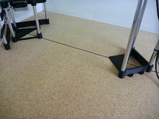
I kept a triangular design to all the component bases in order to help
facilitate in lining all the components together. Bisecting a 90 degree angle
and drawing out the line provides a clear setup for all the pieces.
The electronics driving all this is a lot simpler than it looks. It consists of basically 2 Arduino Duemilanoves, stepper drivers and a simple voltage regulator for the laser. The electronic design is from WalterMo on the David LaserScanner Forums. The schematic and arduino programs can be found here and here. (I’d like to thank him for sharing his work). The only changes I made was to combine the two circuits, removed the 10k resistors from the STEP and DIR inputs and added a switch to ground the MS2 pin on the stepper driver running the laser movement. This latter change gives me a choice of 1/8 and 1/2 step movements and I feel a little more variance.
The controls for the turntable allows for precise rotational setups by degree in both
forward and reverse.
Laser control speed is adjusted by a potentiometer and my additional 1/8 or 1/2
step switch. Movement up or down is also controlled by a switch.


NICE setup and great work. Way to keep it simple, clean and smart. That thing is attractive enough the misses might let us keep one in the living room : )
ReplyDeleteHi
ReplyDeletewow...what a cool setup...I really like your Calibration Panel...do you provide the files for printing them with a 3d Printer maybe? That would be awesome! Regards, Max (maxamsel@gmx.ch)
I haven't posted the parts for sharing. Due to the customization of most of the parts to the mechanical and electronic components I had on hand, I'm not sure how helpful they would be. The beauty of 3D printing is the ability to make what you need to your own specifications.
ReplyDeleteAwesome!
ReplyDeleteWhat's the height of the panels and camera turrets? and the panels size?
Thanks!