Showing posts with label Electronics. Show all posts

Saturday, November 29, 2014

WhiteAnt 3D Printer Build- Final Update

This will be the last overview of modifications I’ve made to the WhiteAnt 3D printer. The system has been running well and needs no more improvements. It’s been a great machine to use for experimentation of various mechanical and electronic systems, but it’s now time to move on.
The first major modification I’ve made has been with the electronics:
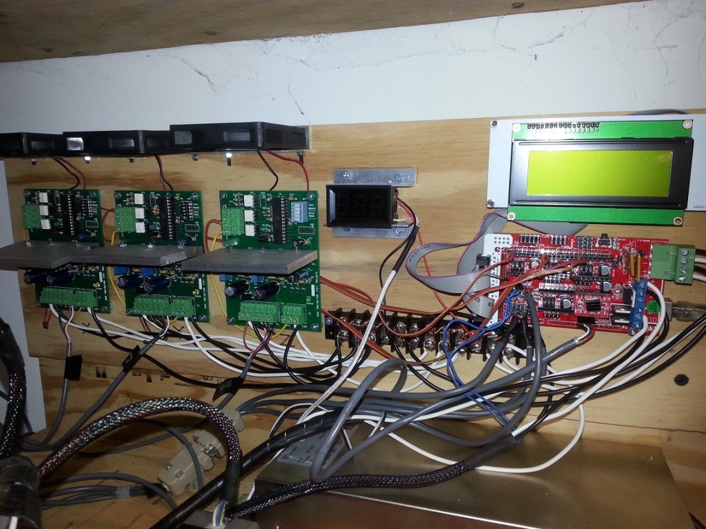
I’ve swapped out the RAMPS 1.2 board for a 1.4 version which allows me to use a Geetech LCD 2004 smart controller. I’ve added a temperature monitor for the build space and I’ve replaced the Makerbot v3.3 stepper drivers (based on the A3977 chip) with the open source designed AVR-Based microstepping bipolar chopper stepper motor driver. This utilizes the National Semiconductor’s LMD18245T 3A, 55V DMOS Full-Bridge Motor driver chips. It’s a robust driver and completely built without surface mounted parts. This gives it an advantage over most drivers because it’s easy to repair. The design can be found here.
I’ve replaced the 6mm T2.5 belts with 9mm T5 belts and 12 tooth pulleys. This, I believe creates a better system for the movement of the XY axes. I also re-designed the pulley system for the X axis.


Last, I’ve created a partial enclosure of the build volume. This allows me to keep some of the heat generated by the build plate and hotend within the build chamber. Now, that I’m in winter months and the ambient temperature of my shop has lowered, this has been important.


Here are a series of sculptures printed with the WhiteAnt. They are 150mm, 100mm and 50mm tall.


Notice the difference in the surface detail between the three models:
Close-up of the 150mm sculpture. The radial pattern is more defined in this largest model.


Close-up of the 100mm sculpture. The radial pattern begins to fade.

Close-up of the 50mm sculpture. The radial pattern is barely discernible.


Here’s a video of the WhiteAnt printing the largest version:


Friday, October 11, 2013

Rostock Delta Robot- Electronics

Assembling the electronics for the Rostock Delta has been achieved with far more ease than any of the other printers I've constructed. The physical design of the printer has much to do with this.

By having all three stepper motors located in close proximity of the Arduino/RAMPS controller, the wiring is  routed more efficiently.


Placing the end stops has been the confusing part. I haven't found any clear information on the placement, and I'm still not sure if I need six or only the three I placed. I'll determine this when I setup the firmware and make the physical calibrations.


The heat bed was simple. There isn't the usual setup of screws and springs. I'm not sure how the leveling will be accomplished, but I’m sure that will also be clarified later.


 I added a 1/4" foam core barrier between the wood base and the heat plate. This should allow for insulation and also enough of an offset allowing for the attachment of a glass plate with clips.


I’m using the old extruder design from my RepRapPro Mendel. It mounts beautifully on the side and allows for perfect positioning of the Bowden cable and the filament feed.


The hot end is the E3D-v5 1.75mm filament version. I downloaded the parts for the mount at thingiverse.com (thing:80616). With a few minor modifications, I made it work. I wanted to be sure the hot end was easily removed with its cabling and Bowden tube, so any future repairs can be made with ease.


Up next, will be software setup and calibration.


Monday, July 22, 2013

Printrbot Electronics

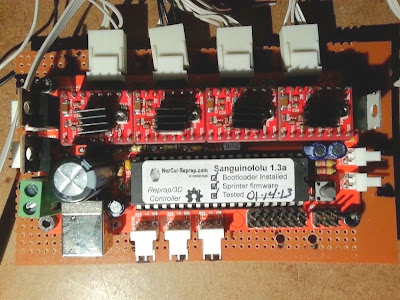
For the Printrbot I've decided to use a Sanguinololu v.1.3a controller. It’s equipped with the ATMEGA 1284 chip and Pololu driver clones.


The primary reason for this setup and not an Arduino Mega with RAMPS shield is because there isn’t much room to place all the components under the print bed. The Sanguinololu is a slim all-in-one unit (minus the drivers).


I added a 4.5" x 6" PCB heat bed.


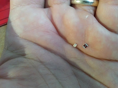
For the LED indictor I  used SMD components.


 Because of their tiny size, it’s not exactly the greatest choice when a soldering iron is the only tool I have, but I found that by adding a little solder flux and adding little mounds of solder to the board connections first is the easiest way to accomplish this. Placing the components next and then heating the connectors with the fine tip of an iron will remelt the solder underneath and make a good bond.


For this printer, I’d like to use a PWM fan. This is a fan that uses pulse-width modulation to control it's speed. Since I plan to be printing with a lot of bridging techniques that may require G-code implemented cooling procedures using a fan, this is a necessity. Unfortunately, the Sanguinololu doesn’t have the required hookup for a PMW fan. To get around this, a separate circuit must be made. I used the circuit outlined here www.thingiverse.com/thing:22202. I did make some changes:  I eliminated the 0.1uF capacitor and swapped out the RF540A MOSFET with a STP55NF06L MOSFET. This is the same MOSFET that’s used on the RAMPS board and is sufficient for use here as well.


This is the first 3D printer replication that I've made. All the plastic parts were made on my Prusa Mendel with some minor parts made with the RepRapPro.


In order to make the electronics work with my preferred host (Printrun) some changes will have to be made in the firmware. This’ll be covered in the next post.

Monday, May 20, 2013

RepRapPro Mendel (Part 6)

I haven't had very good luck with the Melzi board. I burned out the drivers and MOSFETs on my first board (I've never been able to determine the cause). Now I have a burned out heat bed connector. I’m primarily extruding ABS which requires a higher temperature for the bed and I’ve been running the printer for very long periods of time. This may be the reason for this burn out. I’m not
entirely confident that the Melzi board is robust enough for 24 hour runs.


Unfortunately, a simple replacement of the connector isn’t going to work in this case. The burn destroyed the PCB tracing and makes it impossible to solder a new component. In order to have a working bed, I rewired the power leads directly to the power supply and added a switch for manual control. Since no harm has come to the thermistor, I can at least monitor the temperature. This seems to work fine, but I’ve lost automatic control.

I hesitate to buy another Melzi board anytime soon, but if I do I may reinforce the bed connection. A seller of a Sanguinololu board I purchased recently has a recommendation to do exactly this.


The Melzi board is not the only area where I’ve had problems. I’ve also burned out 2 power resistors on the hot end. Once again, I think long periods of operation has taken its toll, but I also suspect that possible damage during installation may also be a factor. Even with additional boring of the hot end’s heat sink, it’s very difficult to install the resistor in the cavity without physically forcing it. This scrapes the surface and causes damage.

Top resistor is the original supplied in the kit and the bottom resistor is from Mouser


The resistors are just too big and coupled with a slight curve in its body, it makes for a difficult fit. I've found a different resistor that works better. It’s slightly narrower, but with a couple wraps of Kapton tape, it makes a snug fit. It can be found at Mouser Electronics:

71-RS2B-2.7/R                             
MFG Part No:RS02B2R700FS70
Vishay Wirewound Resistors

The resistor fits snug from end to end with a couple runs of Kapton tape and a little heat transfer compound


Saturday, February 9, 2013

RepRapPro Mendel (part 3)

I’ve put the MakerGear hot end through hundreds of hours of service without having any problems. Because of this track record, I’m wary of any other system. I've experimented with other hot ends such as the Budaschnozzle and J Head MKIV and I haven't found them to be as reliable.

The RepRapPro hot end will be an interesting new addition and I hope, as reliable as the MakerGear system.

Overall, the assembly was not difficult. The entire system is small and lightweight in comparison to the MakerGear hot end.


The compactness of the hot end assembly can be largely attributed to the system’s employment of a Bowden extruder. Instead of the typical Wades extruder or MakerGear Brutstruder which is attached directly to the hot end and carried on the X carriage, this extruder is mounted on the printer’s frame. The filament is then moved from the extruder to the hot end through an attached PTFE tube. This decreases the weight carried on the X carriage and allows for a greater print speed than the other systems can employ.


The major drawback with using a Bowden cable system is that there can be more oozing and this will leave bumps on the print’s surface. This is due to the increase of springiness in the length of filament that is compressed in the system.
This is my first experience with this type of system and I’m very curious to compare the print results with my other systems.

Electronics

This printer uses the RepRapPro version of the single controller board called the Melzi. It's a board designed to be more plug-and-play and a lower cost alternative to the other controller systems out there. I am not so convinced of this.
RepRapPro Melzi controller

I followed all the test pre-checks with utmost care and found no deviating readings after installing all the electronics. I had full communication through the USB tests with Pronterface, yet when I switched on the 12v supply the drivers and the power supply MOSFET immediately burned.

After checking everything once again, I realized the only mistake I made was that I did not switch the jumper back from USB mode to power supply mode.


Red arrow points to the jumper

According to Adrian at RepRapPro, this should not have burned out the board. I am yet confused as to why this happened.

In the interim, I decided to assemble the alternative, Sanguinololu Rev 1.3a, ATmega 1284P. The drivers I purchased directly from Pololu Robotics. With connectors & USB cable, the entire controller system cost $97 USD.
Sanguinalolu


I ordered a replacement Melzi board from RepRapPro for $139 USD. This is not a cheaper alternative. And coupled with the fact that it's supposed to be an easier controller to use (I have dated, yet formal training in electronics) I managed to burn mine out, so I'm not convinced in its plug-n-play capabilities.

Since my goal is to test this printer as a device that can be used “right out of the box”, I’ve waited for my replacement Melzi board. After carefully transferring all the wiring to the new board, I repeated my pre-check tests and USB communication. Making sure the jumper was moved back to the power supply position, I
turned it on.

Everything is working, all axes are moving smoothly and in the proper directions.

Sunday, September 23, 2012

WhiteAnt 3d Printer Build- Extruder and Hot End

The original WhiteAnt 3d printer specified to use it's own extruder design that is fabricated from wood and a MakerBot hot end. I decided to use a MakerGear plastruder and hot end.

In order to do this I first had to change the heat core of the hot end. The typical MakerGear hot end uses a brass core which is wrapped in nichrome wire and coated with a ceramic adhesive. The 30 awg nichrome wire is cut to length which will give about 6 ohms resistance. In a 12v system this will make a 24 watt heater.

My system is running off of 24v. To achieve the same wattage as the typical MakerGear heat core the total resistance of the nichrome wire will have to be increased. By using Ohm's Law, w=v^2/r=24v^2/24r=24 watts,  it's discovered that the length of the nichrome wire needs to equal 24 ohms (an increased by 4 times). This is a lot of wire to wrap around the brass core. To help decrease the length, I switched to a 31 awg nichrome wire which increases the resistance from 6.5 ohms to 8.2 ohms per foot. This shaved off about a 1/4 of length.


No portion of the WhiteAnt extruder mount is useful for the MakerGear plastruder, so a mounting device had to be designed. I used a Simpson Strong Tie Z-Max Angle and cut a shape which supports the plastruder assembly and  allows for the hot end to protrude from the bottom.


I also added 4 LEDs at the bottom of the plate which will give ample illumination during a print build.


Thursday, September 13, 2012

WhiteAnt 3d Printer Build- Electronics III

Mounted at one end of each axis’ path of travel is a small switch. This is generally referred to as a limit or stop switch and it’s purpose is to signal a “home” point of reference. The original WhiteAnt plans called for the Z-axis switch to be mounted on the bottom end of the X carriage, triggered when the switch makes contact with a screw protruding from the Strong-Tie assembly of the Z-axis. This would make “home” at the furthest point from the printer’s bed.

I find this odd and rather perplexing.

Instead, I replaced one of the bolts holding the Z-axis motor mount assembly with a 3/8” threaded rod cut to a length to where a limit switch could be triggered by a nut. By adjusting the position of the nut on the threaded rod, easy calibration can be made of the extruder’s hot end. The other 2 limit switches were mounted basically as was originally designed.


Before


After


Noise. The fluctuation of electronic signals.

There seems to be a lot of opinion concerning the shielding of noise among CNC users. I don't remember this as a concern when I did research on my Prusa Mendel build. Because I wasn’t aware of using shielded cable, I didn’t and my RepRap printer has worked fine.
I decided to use shielded cable on this printer.


For convenience, I added D-sub connectors so that the electronics can be easily removed from the printer.


Now that I have most of the electronics connected, I did a test drill by running a print routine for a small object. No calibration has been made in the firmware.

Friday, September 7, 2012

WhiteAnt 3d Printer Build- Electronics II

The heart of the 3d printer's electronics system is an Arduino Mega 2560 microcontroller interfaced by a RAMPS 1.2 shield. The RAMPS (RepRap Arduino Mega Pololu Shield) attaches to the topside of the Arduino Mega and allows for connections to the Pololu stepper drivers, motors, heat and fan components. Presently, the version of the board is at 1.4.

Arduino Mega 2560 and Arduino Mega 2560 with attached RAMPS 1.4 shield.


Why am I using a shield designed for Pololu stepper drivers if I plan to use
different drivers? First and foremost, I want to keep with an electronics
package that is working well with the software that I am presently using. My
past experience had a high learning curve because I was completely unfamiliar
with the many different components (both soft and hardware related). Getting all
of it to work together was not easy. I'm hoping by retaining most of my original
setup on this printer, I'll be able to work bugs out more efficiently.

Second, the RAMPS shield is considered to be the best interface for the RepRap printers and because of this, has a good support system (especially where software is concerned).

Third, I plan to retain the use of 1 and later 2 Pololu drivers for extruder
control. More than half of the shield then keeps it’s functionality as it was
designed.

I'm using RAMPS version 1.2 (later I will update to v1.4) for the initial build
of the WhiteAnt. The v1.2 shield was assembled with only one important
alteration:  the IN4004 diode was omitted so that the board can be powered by
24v. All of the driver slots are left in place and will be used as designed.


Fully assembled RAMPS 1.2


Why power the shield with 24v instead of the typical 12v supply? The RepRap
printers use the NEMA 17 stepper motors to move the axes. The WhiteAnt is built
utilizing the larger stepper motors NEMA 23. These larger motors will work more
effectively if more voltage is supplied.

Nema 17 and NEMA 23 stepper motors.


The Pololu 4988 stepper drivers (typically used on the RAMPS shield) are rated
to 35v, 2A and could drive the larger motors, but the higher current demands
would put a strain on them. Overheating would be a constant problem. I'm
replacing the Pololu’s with the v3.3 stepper drivers designed by Makerbot. They
are rated up to 35v, 2.8A and robust enough to handle the NEMA 23's.


Makerbot v3.3 and Pololu 4988 stepper drivers.

The major obstacle in swapping out the Pololu with the Makerbot stepper driver
is the hookup to the RAMPS shield. What connections are necessary? I owe NoobMan on the RepRap forums thanks for helping me sort it out. A detailed account can be found here. Basically, the DIR, STEP, ENABLE pins (ignore the other 3 pins) are connected from the Makerbot driver to the corresponding pins on the RAMPS board (where the Pololu driver would sit).
The 12v power pins on the Makerbot board (even though 24v will be supplied in this case) are connected to the motor power supply pins (where the Pololu would sit) on the RAMPS shield. This supplies power to the Makerbot driver. All of the other connections that the Pololu driver would use can be ignored including the motor connections next to the driver slot. All four stepper motor leads will now be connected directly on the Makerbot driver.

The next obstacle is finding a way to physically attach the connections. One method to solve this is by imitating the Pololu driver. I fabricated little boards with male breakaway headers and wired into it. This gives me the flexibility of swapping  out whatever driver I decide to use.


To test my system, I hooked up a driver and stepper motor to the Y-axis and connected the Arduino Mega to the PC. Using the 3d printer software Pronterface, I was able to run the motor with the y-axis controls. The motor 
worked well in both directions.