I had issues with warping early on when I was in calibration mode with the Prusa Mendel. I solved it by using Kapton tape and In extreme cases with rafting. What I found to be the most helpful was giving the Kapton tape a fine tooth by sanding the surface with swirls. This has given me almost flawless results until now.
Presently, I'm working on pieces that I need for my laser scanner system. One
piece in particular is a thin right angle support that I made as large as I
could fit on the print bed. It spreads 165mm along the x and y axes. It's primary width is 4mm and overall it's 15mm high.
 |
| Printing an angle brace. |
After 3 print runs with warpage, I realized I was back to this old problem. I decided I needed to take the time to solve this. And since I think this may be useful information for others, I'm going to document my 8 print runs.
Prints 1-3
Bed temperature is 72 degrees C.
Ambient temperature is 25 degrees C.
1st print - failed at about 22% completion.
2nd print - Sanded bed slightly. Print failed after about 60% completion.
3rd print - Aggressively sanded more in problem areas. Print failed at about 70%
completion.
I always run my bed with a set temperature of 110 degrees C., but it rarely reaches 83 degrees C. I'm not quite sure why. I double checked the temperature reading of the bed thermistor by checking with an IR thermometer and the readings are close and consistant. Maybe, if I could get my bed temperature up higher it would work?
 |
| Print warps at the end and becomes distorted. |
Print 4
Bed temperature is 72 degrees C.
Ambient temperature is 25 degrees C.
I initiated a raft. Print failed after about 75% completion.
 |
| Printing on a raft dosen't prevent warping in this case. |
Print 5
Bed temperature is 76 degrees C.
Ambient temperature is 27 degrees C.
I calibrated z axis home tight on the print bed so that the filament squeezed
wide. Initiated a raft. Print failed after about 90%
completion. This time only 1 end lifted.
 |
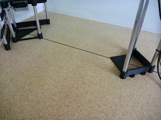
| The bottom raft in this picture is from print 4. It's weave is open. The top raft is from print 5 and is squished tight by the extruder nozzel. |
Print 6
Bed temperature is 81 degrees C.
Ambient temperature is 27 degrees C.
Coated glass with blue tape. Coated the tape with Ace ABS Solvent Cement.
Initiated raft. Print failed due to printer malfunction. After about 35% of print completion I lost a th
ermistor contact and my extruder stopped, so I had to abort the print.
 |
| Blue tape coated with ABS cement. |
Print 7
Bed temperature is 78 degrees C.
Ambient temperature is 29 degrees C.
2nd attempt with using ABS glue. This time I decided to turn rafting off.
I feel cofident that glue is the solution.
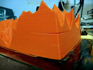
Printing is a success! Print holds well to bed with no warping and without the
use of a raft.
 |
| Print finished with no warping. |
 |
| Close-up reveals very tight bond with bed. |
 |
| Part removed and ready for use. |
Print 8
Bed temperature is 27 degrees C.
Ambient temperature is 29 degrees C.
I ran one more test to see what would happen without a heated bed and only ABS
glue on blue tape.
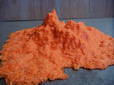
Printing failed!
Print warped after about 60% completion. It adhered strongly to the tape, but
pulled the tape off the glass. It's quite possible that if glue was used on
Kapton tape it would work. That will have to be tried some other day.
 |
| Blue tape lifted. |
In conclusion, for large printing: ABS glue on blue tape with a heated print
bed may be sufficient for all prints within a Prusa Mendel print envelope. Adding a
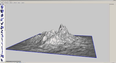
raft should increase this success rate. Later I plan to explore this hypothesis
by maxing out my build envelope with a solid print.
ADDENDUM 6 May 2012:
I increased the height (thus increasing my print time) for my remaining corner braces. This time I did get a problem with one end slightly pulling up the blue tape. I changed over to using Kapton tape with a sanded surface and ABS glue. This has worked for 3 more prints. No warping.
ADDENDUM 25 May 2012
Now that I am printing models which fill the entire print bed, my warping issues have become more problematic. I have not successfully kept the corners from lifting on my prints (averaging 180x180x50mm in size). To minimalize the warping, my system has been to use Kapton tape on glass, sand the surface and coat with ABS glue. Unfortunately, for the size of the print, I am unable to remove it without breaking the glass. My next option (and more favorable) is to use plexiglas instead of glass. I've eliminated the Kapton tape, sand the plexiglass surface and then coat with ABS glue. The plexiglass is more easily removed, but unusable due to warping. In summary, my next possible solution to prevent warping is to build a heat chamber for the printer.
ADDENDUM 20 June 2012
The ambient temperature has increased dramatically this summer and now my bed temperature has occassionally reached 110 degrees C. This has not seemed to help much in preventing warping.
A final note: The ABS glue can be manufactured.
The ACE brand ABS cement contains ABS resin, acetone and MEK.
My homemade ABS glue is the same, but without the MEK. I chopped fine extruder
waste and added it to acetone:
8 grams ABS waste
40 ml acetone
Within several hours I had a nice mix that could be easily brushed.
 |
| ABS scrap |
 |
| Dissolving ABS scrap in acetone. |