Building the Rostock Delta is important for me for a number of reasons:
Overall, the mechanical construction of the Rostock Delta has been the easiest of all the printers I have built. One of the major factors for this ease has been the wood support components. I downloaded dxf files of the wood members (thing:34570) and simplified the design by eliminating the intricate “crown shape” cuts which allow fastening by screw and nut. I then had a local sign shop CNC router the pieces out of MDO. This obviously provided me with perfect angles and drilled holes for the placement of plastic parts I printed on my Mendel Prusa (thing:17175).
I couldn’t find specific assembly instructions for this printer, except for the Bill of Materials list (referenced by the RepRap Rostock Wiki). I think, with some previous knowledge of a RepRap build, it’s easy to figure out.
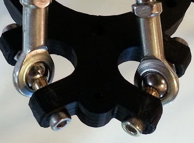
I made a choice early on to upgrade the printed arms with bearing arms and set screws that I purchased on eBay.

This was a very good move on my part. The fluid mobility of the joints are superb.

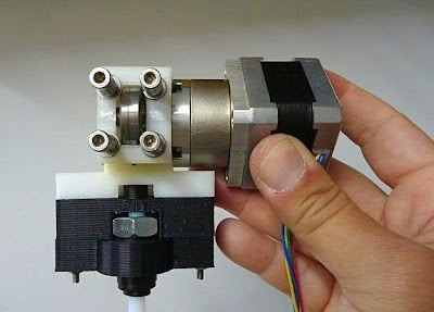
I also equipped the stepper motors with 40 tooth GT2 plastic pulleys rather than the 8 and 20 tooth aluminum pulleys that I’m using on my other printers. This may or not be better. The original specs for the Rostock called for the 40 tooth pulley. I've later discovered since purchasing the GT2's, that they'll have less torque and a lower resolution than smaller pulleys. On the upswing, the GT2 belts and pulleys are designed for linear motion and this will eliminate the backlash which my T2.5 and T5 pulleys are prone to exhibit.

Overall, a very sturdy design. I’m looking forward to getting it moving.

- First, the simplicity of the design. Eventually, if all goes well, I’ll need to build larger machines. This design may prove to be the easiest route to take.
- Second, I plan to experiment with faster printing speeds and faster printing speeds with larger nozzle sizes. The Rostock boasts a positioning speed of 800 mm/s in all three directions.
- Third, the manner in which the electronics and stepper motors are shielded from the printer mechanics seem optimal for creating a temperature controlled chamber.
- Fourth, the bed remains stationary. This will be very important when I’m prepared to set up a system for clay extrusion. I’m certain that with the typical RepRap printer the motion of a build platform while extruding clay (especially large models) would become problematic. The Delta design will eliminate this situation.
Overall, the mechanical construction of the Rostock Delta has been the easiest of all the printers I have built. One of the major factors for this ease has been the wood support components. I downloaded dxf files of the wood members (thing:34570) and simplified the design by eliminating the intricate “crown shape” cuts which allow fastening by screw and nut. I then had a local sign shop CNC router the pieces out of MDO. This obviously provided me with perfect angles and drilled holes for the placement of plastic parts I printed on my Mendel Prusa (thing:17175).
I couldn’t find specific assembly instructions for this printer, except for the Bill of Materials list (referenced by the RepRap Rostock Wiki). I think, with some previous knowledge of a RepRap build, it’s easy to figure out.
I made a choice early on to upgrade the printed arms with bearing arms and set screws that I purchased on eBay.
This was a very good move on my part. The fluid mobility of the joints are superb.
I also equipped the stepper motors with 40 tooth GT2 plastic pulleys rather than the 8 and 20 tooth aluminum pulleys that I’m using on my other printers. This may or not be better. The original specs for the Rostock called for the 40 tooth pulley. I've later discovered since purchasing the GT2's, that they'll have less torque and a lower resolution than smaller pulleys. On the upswing, the GT2 belts and pulleys are designed for linear motion and this will eliminate the backlash which my T2.5 and T5 pulleys are prone to exhibit.
Overall, a very sturdy design. I’m looking forward to getting it moving.