Showing posts with label WhiteAnt. Show all posts

Saturday, November 29, 2014

WhiteAnt 3D Printer Build- Final Update

This will be the last overview of modifications I’ve made to the WhiteAnt 3D printer. The system has been running well and needs no more improvements. It’s been a great machine to use for experimentation of various mechanical and electronic systems, but it’s now time to move on.
The first major modification I’ve made has been with the electronics:

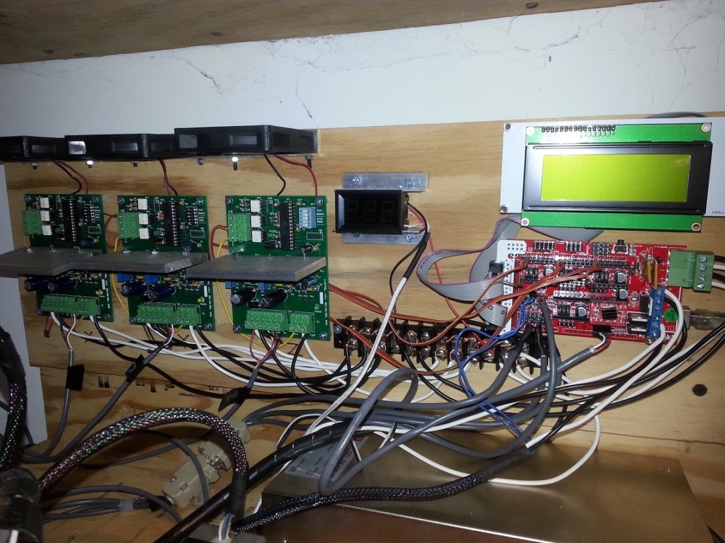
I’ve swapped out the RAMPS 1.2 board for a 1.4 version which allows me to use a Geetech LCD 2004 smart controller. I’ve added a temperature monitor for the build space and I’ve replaced the Makerbot v3.3 stepper drivers (based on the A3977 chip) with the open source designed AVR-Based microstepping bipolar chopper stepper motor driver. This utilizes the National Semiconductor’s LMD18245T 3A, 55V DMOS Full-Bridge Motor driver chips. It’s a robust driver and completely built without surface mounted parts. This gives it an advantage over most drivers because it’s easy to repair. The design can be found here.
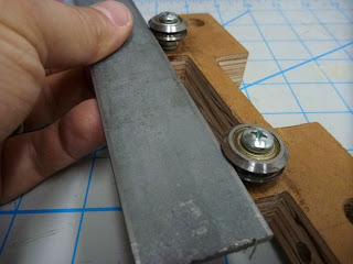
I’ve replaced the 6mm T2.5 belts with 9mm T5 belts and 12 tooth pulleys. This, I believe creates a better system for the movement of the XY axes. I also re-designed the pulley system for the X axis.


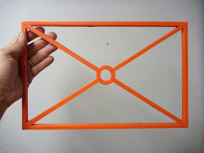
Last, I’ve created a partial enclosure of the build volume. This allows me to keep some of the heat generated by the build plate and hotend within the build chamber. Now, that I’m in winter months and the ambient temperature of my shop has lowered, this has been important.


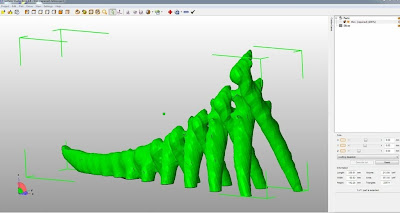
Here are a series of sculptures printed with the WhiteAnt. They are 150mm, 100mm and 50mm tall.


Notice the difference in the surface detail between the three models:
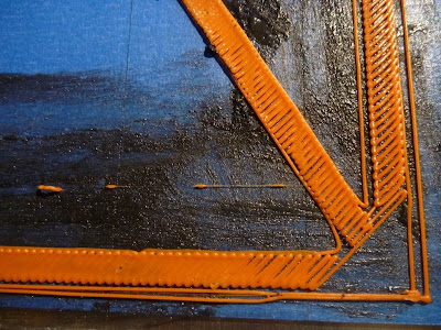
Close-up of the 150mm sculpture. The radial pattern is more defined in this largest model.


Close-up of the 100mm sculpture. The radial pattern begins to fade.

Close-up of the 50mm sculpture. The radial pattern is barely discernible.


Here’s a video of the WhiteAnt printing the largest version:


Wednesday, November 21, 2012

WhiteAnt 3d Printer Build- Redesigning the Y-Axis

The original WhiteAnt design utilizes 3/8" V-groove bearings for the Y-axis movement. It works by sliding a metal strap (that's attached to the side of the printer’s bed) in and along the V-groove of the bearings. The motor and belt system is located to the left of the bed.


This system may be fine for the original design, but has always been a concern for me since I increased the bed size from 8 9/16" x 9 1/16" to 12" x 17". Pulling the bed from one side with the V-groove bearing system creates wobble in the bed and there’s more vibration in the printer as a whole.

My solution to this problem has been to replace the entire bearing system with a different design. I'm using (2) 16mm linear shafts with 4 slide bearings which I mounted to the base of the printer. This eliminates any stress on the printer’s  structure and it provides more precision in its movement.


I kept the motor and belt system as originally designed: it's a belt stretched across both ends of the Y-axis length of travel and powered by the motor’s pulley in the middle. Tension is created by 2 idler pulleys (made from bearings) pulling the belt around the motor’s pulley in a  S-shaped curve.


Keeping this design was not a good idea. I don't have the optimum clearance for the belt and there is undue stress on the belt when the bed fully extends on its axis.


My first test print with this new setup ended with disaster. Not only am I still getting distortion in my print, but I lost Y-axis movement about half way through the print. Something must have snagged the belt and stretched it out of shape.


1st print run.


I decided to use a belt drive system similar to what is utilized on the Prusa Mendel 3d printer.

I fabricated a motor mount and an idler pulley tensioner system from Simpson Tie angle brackets. I ran the belt around the pulleys and attached the ends to the printer’s bed forming a large loop.


The second print test is better after the belt drive system change, but there is still some distortion. The infill doesn't cover completely across the print in areas, leaving an open space along the perimeter wall.


2nd print run.


2nd print run. Wavy lines cause irregular perimeter surface.


I tighten the belts and started a third print test. This time the distorted has cleared and the print seems flawless.


3rd print run. A much better print.
3rd print run.


A lot of print distortion can clearly be the cause of poor axis alignment and obstruction. Probably the most common problems are caused by inadequate belt tension that causes backlash in the belt system.

I don't have a completed test print this time for one reason: warping. Once again, I have the problematic issue of controlling the curling ends of my large prints. I plan to tackle this more aggressively and show my results in my next entry.


Monday, October 8, 2012

WhiteAnt 3d Printer Build- Print Volume Test


Since my plan is to eventually print sculptures that are primarily organic in form, I decided to create a more interesting test print (rather than the basic geometric forms I've been using lately).

Earlier this year, I used Bryce 7 Pro to create some fractal based landscapes which filled the print bed of my Prusa Mendel 3d printer. It was a quick modeling solution, but I think this time not appropriate for this particular test. The print time for a Bryce Pro landscape on this printer would take days, rather than hours.


My solution this time for creating a test model is a freeware program called Incendia Ex. It's a traditional fractal generator that has the very useful function of allowing a generated form to be saved as an .obj or .stl file.


Incendia Ex


Once I had a 3d model generated by Incendia Ex, I then needed to import it to a 3d modeling program for modification. Most of my experience using 3d modeling software to date has been with Google SketchUp. It’s great for designing 3d printable forms when they are mechanical in nature, but not for organic models. I need  a sculpting program that has an artist in mind.


Hexagon 2.5

I’m using Hexagon 2.5 from Daz3d. It's not my first pick of 3d modeling programs, but it’s presently given away free from the software company ( it’s fully functional with a serial number). With Hexagon, I was able to slice forms apart, tighten their connections for structural integrity and cap holes.


Netfabb

With the model complete, I had one last step to prepare it for printing. I imported it into the free version of Netfabb. This program basically repaired the mesh of my model of small holes or non-manifold geometry. In order  for the model to print correctly, the 3d model’s mesh must be clean and watertight.


The model's size is 330mmx60mmx142mm (13"x2-3/8"x5-1/2”) and took 5 1/2 hours to print.


Sunday, October 7, 2012

WhiteAnt 3d Printer Build- Full Height Test Print


I created a cylinder in Google SketchUp that is 145mm tall and 40mm wide for this test.


Critique:
Overall the the print is fine. 

Saturday, September 29, 2012

WhiteAnt 3d Printer Build- Full Bed Test Print

This test will use the maximum printable area of the print bed which is 360mm x 240mm. I  created a model in Google SketchUp that fills an area 350mm x 220mm (13.8" x 8.7"). The walls are 10mm high and 8mm thick and the outer diameter of the circle is 40mm.


Here is the print data:

Extruder Nozzle: .5mm
Print Layer Thickness: .4mm
25 layers
Infill solidity ratio: 0.1
77,750 lines
15,670 filament length
Heat bed (center ref. point) temp. 61-65c
Ambient temp. 27.5c
Print Time: 4hr 32min


Critique:

Overall the first print run using the full bed was a success, but there are some trouble points that need to be mentioned.
1) a fine tuning of the axes calibration if precise pieces are required. The
X-axis measures 350mm as the model, but the Y-axis measures 5mm wider.
2) slight warping at the corners, but unobtrusive overall.


3) an odd separation of the perimeter walls toward the bottom right hand corner.


4) about 30mm inward from all 4 corner points the printing is rough.


Thursday, September 27, 2012

WhiteAnt 3d Printer Build- Calibration

I spent a long time working out the calibration on my Mendel Prusa 3d printer. I had numerous problems with the electronics and the software and I didn’t have a working reference point to help solve them. This is one reason why I kept many of the familiar systems of my Prusa Mendel printer as a part of this modified WhiteAnt printer.

The calibration for the modified WhiteAnt hasn’t been difficult.

I'm using Kiliment-Sprinter-a352585 firmware with  Pronterface. Here are the following changes I made from my Prusa Mendel setup:
In Pronterface, I increased the print bed. This can be done by opening the options window from the settings tab and changing the build dimensions. In my case, instead of 200mm x 200mm x 80mm, I placed the values 360mm x 240mm x150mm.

In the firmware, I changed the build envelope size. Under the tab Configuration.h these values were substituted:
Const int X_MAX_LENGTH = 360;
Const int Y_MAX_LENGTH = 240;
Const int Z_MAX_LENGTH = 150;

Next I set the calibration for the X,Y,Z, and E steps. For my Prusa Mendel they were:
axis_steps_per_unit[] = {79.207, 80, 2568, 1394};
For the modified WhiteAnt the values were substituted with these:
axis_steps_per_unit[] = {39.9, 40.90, 329, 1300};

Interestingly, the X,Y values are half of the original values when the stepper motor is increased one size up. The Z-axis is way off due to changing from a metric 8mm rod with a 1.25 pitch to a SAE 3/8" lead screw with 10 threads per inch. The extruder is basically the same since no change in that system was made.


These are all of the changes that I made. All my previous Skeinforge and Pronterface settings I left in place. There is always room for improvement, but for now I’m happy to keep my setup at it’s present configuration. 


Tuesday, September 25, 2012

WhiteAnt 3d Printer Build- Reinforcing the Structure

It's not fair for me to criticize the structural integrity of the WhiteAnt design because I modified it and since I haven’t built the original design (or physically seen it in action), I have no basis to make an opinion. My modified WhiteAnt needs structural reinforcement. There is severe vibration along the x-axis and the legs of the printer during xy-axis movement.

In order to dampen this, I mounted the legs to a base made of 3/4" thick MDF.


The back plate of the printer is screwed into a box which covers the back end of
the printer (where the print bed extends along the y-axis). This adds substantial
support to x-axis rail.


Sunday, September 23, 2012

WhiteAnt 3d Printer Build- Extruder and Hot End

The original WhiteAnt 3d printer specified to use it's own extruder design that is fabricated from wood and a MakerBot hot end. I decided to use a MakerGear plastruder and hot end.

In order to do this I first had to change the heat core of the hot end. The typical MakerGear hot end uses a brass core which is wrapped in nichrome wire and coated with a ceramic adhesive. The 30 awg nichrome wire is cut to length which will give about 6 ohms resistance. In a 12v system this will make a 24 watt heater.

My system is running off of 24v. To achieve the same wattage as the typical MakerGear heat core the total resistance of the nichrome wire will have to be increased. By using Ohm's Law, w=v^2/r=24v^2/24r=24 watts,  it's discovered that the length of the nichrome wire needs to equal 24 ohms (an increased by 4 times). This is a lot of wire to wrap around the brass core. To help decrease the length, I switched to a 31 awg nichrome wire which increases the resistance from 6.5 ohms to 8.2 ohms per foot. This shaved off about a 1/4 of length.


No portion of the WhiteAnt extruder mount is useful for the MakerGear plastruder, so a mounting device had to be designed. I used a Simpson Strong Tie Z-Max Angle and cut a shape which supports the plastruder assembly and  allows for the hot end to protrude from the bottom.


I also added 4 LEDs at the bottom of the plate which will give ample illumination during a print build.


Thursday, September 13, 2012

WhiteAnt 3d Printer Build- Electronics III

Mounted at one end of each axis’ path of travel is a small switch. This is generally referred to as a limit or stop switch and it’s purpose is to signal a “home” point of reference. The original WhiteAnt plans called for the Z-axis switch to be mounted on the bottom end of the X carriage, triggered when the switch makes contact with a screw protruding from the Strong-Tie assembly of the Z-axis. This would make “home” at the furthest point from the printer’s bed.

I find this odd and rather perplexing.

Instead, I replaced one of the bolts holding the Z-axis motor mount assembly with a 3/8” threaded rod cut to a length to where a limit switch could be triggered by a nut. By adjusting the position of the nut on the threaded rod, easy calibration can be made of the extruder’s hot end. The other 2 limit switches were mounted basically as was originally designed.


Before


After


Noise. The fluctuation of electronic signals.

There seems to be a lot of opinion concerning the shielding of noise among CNC users. I don't remember this as a concern when I did research on my Prusa Mendel build. Because I wasn’t aware of using shielded cable, I didn’t and my RepRap printer has worked fine.
I decided to use shielded cable on this printer.


For convenience, I added D-sub connectors so that the electronics can be easily removed from the printer.


Now that I have most of the electronics connected, I did a test drill by running a print routine for a small object. No calibration has been made in the firmware.