Showing posts with label Video. Show all posts

Monday, October 8, 2012

WhiteAnt 3d Printer Build- Print Volume Test


Since my plan is to eventually print sculptures that are primarily organic in form, I decided to create a more interesting test print (rather than the basic geometric forms I've been using lately).

Earlier this year, I used Bryce 7 Pro to create some fractal based landscapes which filled the print bed of my Prusa Mendel 3d printer. It was a quick modeling solution, but I think this time not appropriate for this particular test. The print time for a Bryce Pro landscape on this printer would take days, rather than hours.


My solution this time for creating a test model is a freeware program called Incendia Ex. It's a traditional fractal generator that has the very useful function of allowing a generated form to be saved as an .obj or .stl file.


Incendia Ex


Once I had a 3d model generated by Incendia Ex, I then needed to import it to a 3d modeling program for modification. Most of my experience using 3d modeling software to date has been with Google SketchUp. It’s great for designing 3d printable forms when they are mechanical in nature, but not for organic models. I need  a sculpting program that has an artist in mind.


Hexagon 2.5

I’m using Hexagon 2.5 from Daz3d. It's not my first pick of 3d modeling programs, but it’s presently given away free from the software company ( it’s fully functional with a serial number). With Hexagon, I was able to slice forms apart, tighten their connections for structural integrity and cap holes.


Netfabb

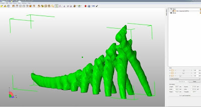
With the model complete, I had one last step to prepare it for printing. I imported it into the free version of Netfabb. This program basically repaired the mesh of my model of small holes or non-manifold geometry. In order  for the model to print correctly, the 3d model’s mesh must be clean and watertight.


The model's size is 330mmx60mmx142mm (13"x2-3/8"x5-1/2”) and took 5 1/2 hours to print.


Sunday, October 7, 2012

WhiteAnt 3d Printer Build- Full Height Test Print


I created a cylinder in Google SketchUp that is 145mm tall and 40mm wide for this test.


Critique:
Overall the the print is fine. 

Saturday, September 29, 2012

WhiteAnt 3d Printer Build- Full Bed Test Print

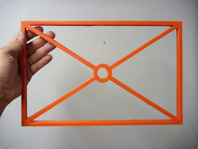
This test will use the maximum printable area of the print bed which is 360mm x 240mm. I  created a model in Google SketchUp that fills an area 350mm x 220mm (13.8" x 8.7"). The walls are 10mm high and 8mm thick and the outer diameter of the circle is 40mm.


Here is the print data:

Extruder Nozzle: .5mm
Print Layer Thickness: .4mm
25 layers
Infill solidity ratio: 0.1
77,750 lines
15,670 filament length
Heat bed (center ref. point) temp. 61-65c
Ambient temp. 27.5c
Print Time: 4hr 32min


Critique:

Overall the first print run using the full bed was a success, but there are some trouble points that need to be mentioned.
1) a fine tuning of the axes calibration if precise pieces are required. The
X-axis measures 350mm as the model, but the Y-axis measures 5mm wider.
2) slight warping at the corners, but unobtrusive overall.


3) an odd separation of the perimeter walls toward the bottom right hand corner.


4) about 30mm inward from all 4 corner points the printing is rough.


Thursday, September 27, 2012

WhiteAnt 3d Printer Build- Calibration

I spent a long time working out the calibration on my Mendel Prusa 3d printer. I had numerous problems with the electronics and the software and I didn’t have a working reference point to help solve them. This is one reason why I kept many of the familiar systems of my Prusa Mendel printer as a part of this modified WhiteAnt printer.

The calibration for the modified WhiteAnt hasn’t been difficult.

I'm using Kiliment-Sprinter-a352585 firmware with  Pronterface. Here are the following changes I made from my Prusa Mendel setup:
In Pronterface, I increased the print bed. This can be done by opening the options window from the settings tab and changing the build dimensions. In my case, instead of 200mm x 200mm x 80mm, I placed the values 360mm x 240mm x150mm.

In the firmware, I changed the build envelope size. Under the tab Configuration.h these values were substituted:
Const int X_MAX_LENGTH = 360;
Const int Y_MAX_LENGTH = 240;
Const int Z_MAX_LENGTH = 150;

Next I set the calibration for the X,Y,Z, and E steps. For my Prusa Mendel they were:
axis_steps_per_unit[] = {79.207, 80, 2568, 1394};
For the modified WhiteAnt the values were substituted with these:
axis_steps_per_unit[] = {39.9, 40.90, 329, 1300};

Interestingly, the X,Y values are half of the original values when the stepper motor is increased one size up. The Z-axis is way off due to changing from a metric 8mm rod with a 1.25 pitch to a SAE 3/8" lead screw with 10 threads per inch. The extruder is basically the same since no change in that system was made.


These are all of the changes that I made. All my previous Skeinforge and Pronterface settings I left in place. There is always room for improvement, but for now I’m happy to keep my setup at it’s present configuration. 


Thursday, September 13, 2012

WhiteAnt 3d Printer Build- Electronics III

Mounted at one end of each axis’ path of travel is a small switch. This is generally referred to as a limit or stop switch and it’s purpose is to signal a “home” point of reference. The original WhiteAnt plans called for the Z-axis switch to be mounted on the bottom end of the X carriage, triggered when the switch makes contact with a screw protruding from the Strong-Tie assembly of the Z-axis. This would make “home” at the furthest point from the printer’s bed.

I find this odd and rather perplexing.

Instead, I replaced one of the bolts holding the Z-axis motor mount assembly with a 3/8” threaded rod cut to a length to where a limit switch could be triggered by a nut. By adjusting the position of the nut on the threaded rod, easy calibration can be made of the extruder’s hot end. The other 2 limit switches were mounted basically as was originally designed.


Before


After


Noise. The fluctuation of electronic signals.

There seems to be a lot of opinion concerning the shielding of noise among CNC users. I don't remember this as a concern when I did research on my Prusa Mendel build. Because I wasn’t aware of using shielded cable, I didn’t and my RepRap printer has worked fine.
I decided to use shielded cable on this printer.


For convenience, I added D-sub connectors so that the electronics can be easily removed from the printer.


Now that I have most of the electronics connected, I did a test drill by running a print routine for a small object. No calibration has been made in the firmware.

Thursday, March 15, 2012